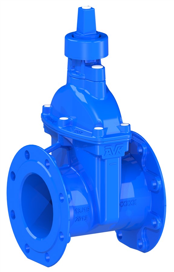
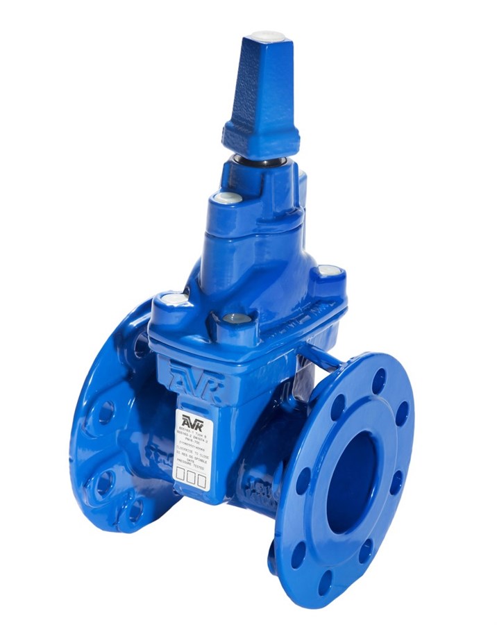
AVK RESILIENT SEATED GATE VALVE, PN16
Ductile iron, with stem cap/Insert

Mamoun Humayra
Water Product Manager
Resilient seat gate valve for water and waste water. Temperature range: -10° C to +70° C. 10% solid matter, Insulation essential for temperatures of 0° C and below. Maximum working pressure: 16 bar.
The 21/35 is a resilient seat, wedge gate valve for isolation purposes suitable for use with water and neutral liquids (sewage) to a maximum temperature of up to +70°C.
| Variant 21/35-001 | |
|---|---|
| Connection: | Flanged |
| Material: | Ductile Iron |
| DN: | DN50 - DN400 |
| PN: | PN 16 |
Features
- Cap top as standard.
- The ductile iron wedge, fully vulcanized with EPDM rubber.
- O-ring stem seals replaceable under pressure.
- Fully corrosion resistant construction.
- Blue fusion bonded epoxy coating.
- Body, bonnet and gland bolts sealed with hot melt
- Lifting bars.
- Patent pending.
- Internal holiday free coating.
- Options:
- ISO flange gland version for gearbox and actuator mounting (21/37 and 21/79).
- Clock wise to open (red stem cap insert), clock wise to close (white stem cap insert).
- Version available for salt laden environments (21/58).
- Bypass valve available on DN350 & 400 sizes.
- Safety Note:
- The valves now accommodate lifting bars for the safe handling of valves. These lifting bars are rated to the weight of the bare valve and stem cap (where fitted) only and should not be utilised if the valve is fitted with pipe, mechanical pipe joints, gearboxes, actuators or any other external fitment. AVK will not accept any responsibility for loss or damage if the lifting bars are not used in strict accordance with this guidance.
Downloads
Datasheet
Related Datasheets
Tender Text
Certificate(s)
Installation, Operation & Maintenance
Guidelines
Price list
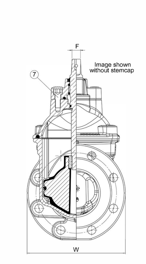
Reference nos. and dimensions:
Scroll for more info
| Ref. no. | DN mm |
Flange drillling |
Operating Direction |
L mm |
H mm |
W mm |
H3 mm |
F mm |
Bolt No. |
Turns to open |
Theoretical weight/kg |
Notes |
|---|---|---|---|---|---|---|---|---|---|---|---|---|
| 21-050-35-2140069 | 50 | PN10/16 | CTC | 178 | 318 | 165 | 400 | 19 | 4 | 5 | 14 | |
| 21-050-35-3140069 | 50 | PN10/16 | CTO | 178 | 318 | 165 | 400 | 19 | 4 | 5 | 14 | |
| 21-080-35-2140069 | 80 | PN10/16 | CTC | 203 | 318 | 203 | 413 | 19 | 8 | 7.5 | 14 | |
| 21-080-35-3140069 | 80 | PN10/16 | CTO | 203 | 318 | 203 | 413 | 19 | 8 | 7.5 | 14 | |
| 21-100-35-2140069 | 100 | PN10/16 | CTC | 229 | 338 | 229 | 443 | 19 | 8 | 8.5 | 17 | |
| 21-100-35-3140069 | 100 | PN10/16 | CTO | 229 | 338 | 229 | 443 | 19 | 8 | 8.5 | 17 | |
| 21-150-35-2140069 | 150 | PN10/16 | CTC | 267 | 428 | 267 | 563 | 19 | 8 | 12.5 | 29 | |
| 21-150-35-3140069 | 150 | PN10/16 | CTO | 267 | 428 | 267 | 563 | 19 | 8 | 12.5 | 29 | |
| 21-200-35-2140069 | 200 | PN16 | CTC | 292 | 515 | 292 | 681 | 19 | 12 | 16.5 | 47 | |
| 21-200-35-3140069 | 200 | PN16 | CTO | 292 | 515 | 292 | 681 | 19 | 12 | 16.5 | 47 | |
| 21-250-35-2140069 | 250 | PN16 | CTC | 330 | 662 | 400 | 862 | 27 | 12 | 21 | 84 | |
| 21-250-35-3140069 | 250 | PN16 | CTO | 330 | 662 | 400 | 862 | 27 | 12 | 21 | 84 | |
| 21-300-35-2140069 | 300 | PN16 | CTC | 356 | 739.5 | 455 | 967 | 27 | 12 | 25 | 117 | |
| 21-300-35-3140069 | 300 | PN16 | CTO | 356 | 739.5 | 455 | 967 | 27 | 12 | 25 | 117 | |
| 21-350-35-2140069 | 350 | PN16 | CTC | 381 | 821 | 554 | 1088 | 32 | 16 | 27 | 214 | |
| 21-350-35-3140069 | 350 | PN16 | CTO | 381 | 821 | 554 | 1088 | 32 | 16 | 27 | 214 | |
| 21-350-35-G140069 | 350 | PN16 | CTC | 381 | 821 | 554 | 1088 | 32 | 16 | 27 | 225 | G - bypass fitted to CTC valve |
| 21-350-35-H140069 | 350 | PN16 | CTO | 381 | 821 | 554 | 1088 | 32 | 16 | 27 | 225 | H - bypass fitted to CTO valve |
| 21-400-35-2140069 | 400 | PN16 | CTC | 406 | 406 | 580 | 1138 | 32 | 16 | 29 | 220 | |
| 21-400-35-3140069 | 400 | PN16 | CTO | 406 | 848 | 580 | 1138 | 32 | 16 | 29 | 220 | |
| 21-400-35-G140069 | 400 | PN16 | CTC | 406 | 848 | 580 | 1138 | 32 | 16 | 29 | 231 | G - bypass fitted to CTC valve |
| 21-400-35-H140069 | 400 | PN16 | CTO | 406 | 406 | 580 | 1138 | 32 | 16 | 29 | 231 | H - bypass fitted to CTO valve |
3D drawings
Enquiry
Scroll for more info
Components
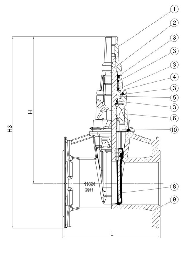
| 1. | Stem Cap | Cast iron GJL-250 |
| 2. | Stem | Stainless steel 1.4021 |
| 3. | Seal | NBR rubber |
| 4. | Gland Flange Assembly | Ductile Iron GJS-500-7 |
| 5. | Thrust collar | DZR brass |
| 6. | Bonnet | Ductile Iron GJS-500-7 |
| 7. | Bolt | Steel 8.8 |
| 8. | Wedge | Ductile Iron GJS-500-7 |
| 9. | Body | Ductile Iron GJS-500-7 |
| 10. | Bonnet gasket | EPDM |
| 11. | Coating | Epoxy |
Test/Approvals
- Hydraulic test according to EN 1074-1 / EN 12266
- Approved according to WRAS
- Drinking Water Inspectorate Regulation 31 compliant
- Made in Great Britain
Standards
- Designed according to BS5163/B, Designed according to BS EN 1074 -1 and 2
- Face to face according to EN 558 Table 2 Basic Series 3
- Standard flange drilling to EN1092 (ISO 7005-2), PN 16