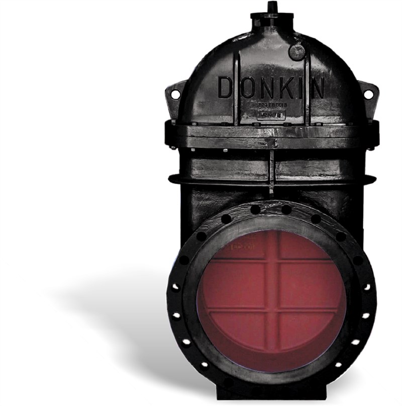
Donkin Series 555D Ductile Iron Gate Valves PN7
Flanged Gate Valve to GIS/V7:Part 1

Andy Hatton
National Sales Manager – Gas
Flanged Gate Valve to GIS/V7:Part 1. Maximum Working Pressure: 7 Bar (100 PSIG), Temperature Range: -10°C to +60°C
The large diameter Series 555 Softseal Valve is a double-faced, resilient seat, internal screw, clear bore wedge gate valve. It is designed primarily for the isolation of natural gas and manufactured gas. Manufactured and approved to specification GIS/V7:Part 1
The Donkin 555 softseal gas valves are manufactured with the tried and trusted Donkin metallic wedge used for over 50 years on the gas networks. A true wedge design, the gate seals on both machined faces with an embedded nitrile seal in each face which sit completely outside the flow of gas with the valve open.
• The design gives effective and long term sealing on closure and the closing torques remain relatively low over the valve’s design life.
• The low closing / breaking torque means operators don’t risk over exertion / injury. Can be easily closed by a single person with standard equipment.
• Negates the need for manual handling risk assessment.
| Variant 555/101-001 | |
|---|---|
| Connection: | Flanged |
| Material: | Ductile Iron |
| DN: | DN400 - DN600 |
| PN: | PN 7 |
| Closing direction: | Clockwise to Close |
Features
- Soft seal, positive shut off
- Full double block and bleed with pressure relieving plug
- Clear bore for under pressure drilling operations
- Metal to metal secondary seal
- Maintenance free
- “Flange feet” to aid installation and stockholding
- No lubrication required
- Double ‘O’ Ring stem seal
- Lifting lugs on all sizes
- Suitable for above and below ground use
- Embodied carbon data available upon request.
- Options:
- Pressure point/by-pass bosses cast into the valve as standard. These can be drilled and plugged at our factory if required
- Viton Seals
- Alternative flange drilling
- Bare shaft end
- Gearbox
- Electric/pneumatic actuation
- Stainless steel spindle
Downloads
Reference nos. and dimensions:
| Ref. no. | DN mm |
H3 mm |
H mm |
HF mm |
BR DN |
By-pass DN |
L mm |
Turns to open |
Theoretical weight/kg |
|---|---|---|---|---|---|---|---|---|---|
| 555-400-00-011 | 400 | 1133 | 864 | 927 | RP0.75 | RP1.5 | 406 | 36 | 301 |
| 555-450-00-011 | 450 | 1274 | 947 | 1010 | RP0.75 | RP1.5 | 432 | 40 | 340 |
| 555-600-00-011 | 600 | 1617 | 1189 | 1252 | RP0.75 | RP2 | 508 | 52 | 745 |
Components
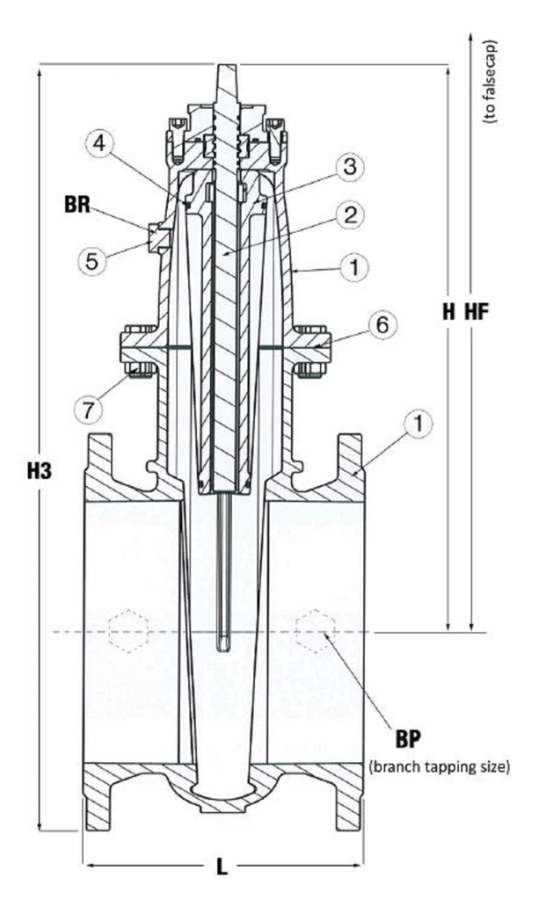
| 1. | Body and bonnet | Ductile iron GJS-450-10 |
| 2. | Stem | Steel 11SMn30 (EN1A) |
| 3. | Gate | Cast iron GJL-250 |
| 4. | Stem/seat seal | NBR rubber |
| 5. | Pressure relief plug | Steel 11SMn30 (EN1A) |
| 6. | Bonnet gasket | CNAF fibres |
| 7. | Fasteners | Steel 8.8 |
Test/Approvals
- Tested according to EN12266-1
- Approved according to Kitemark™ GIS/V7-1, certificate KM 518241
- Made in Great Britain
- CE marked according to Pressure Equipment Directive
- UKCA marked according to Pressure Equipment Regulations
Standards
- GIS/V7 Part 1
- Face to face according to EN 558 Table 2 Basic Series 3
- Standard flange drilling to EN1092 (ISO 7005-2), PN 16
-
GIS/V7:Part 1