Donkin Series 555 Ductile Iron Gate Valves, 10 Bar
Flanged Ends GIS/V7:Part 1 DI body & bonnet

Andy Hatton
National Sales Manager – Gas
Flanged Gate Valve to GIS/V7:Part 1. 10 bar. Maximum Working Pressure: 555/301 - 10 Bar (145 psig). Temperature Range: -10°C to +60°C
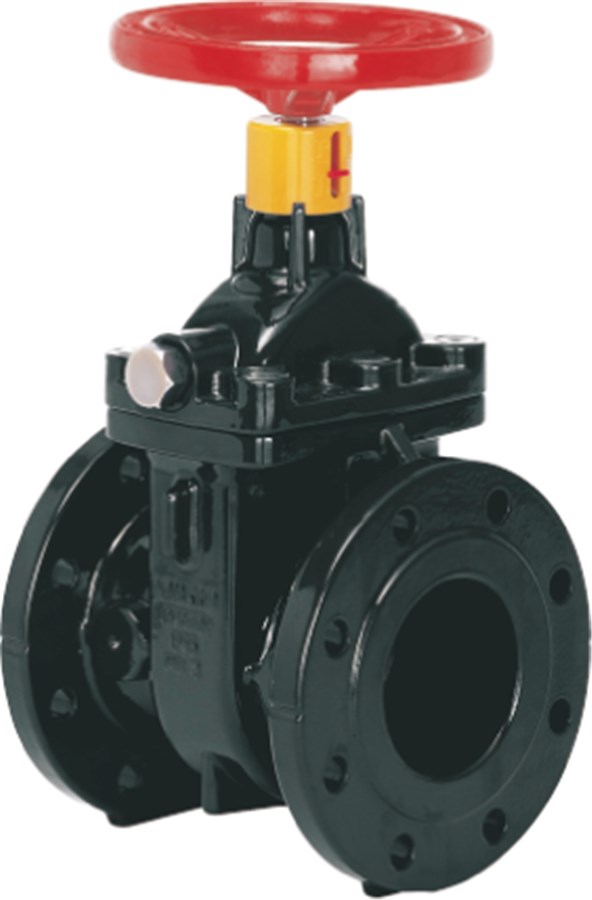
The Series 555/301 Softseal Valve is a double-faced, resilient seat, internal screw, clear bore wedge gate valve. It is designed primarily for the isolation of natural gas and manufactured gas. Manufactured and approved to specification GIS/V7:Part 1
The Donkin 555 softseal gas valves are manufactured with the tried and trusted Donkin metallic wedge used for over 50 years on the gas networks. A true wedge design, the gate seals on both machined faces with an embedded nitrile seal in each face which sit completely outside the flow of gas with the valve open.
• The design gives effective and long term sealing on closure and the closing torques remain relatively low over the valve’s design life.
• The low closing / breaking torque means operators don’t risk over exertion / injury. Can be easily closed by a single person with standard equipment.
• Negates the need for manual handling risk assessment.
| Variant 555/301-001 | |
|---|---|
| Connection: | Flanged |
| Material: | Ductile Iron |
| DN: | DN80 - DN300 |
| PN: | PN 10 |
| Closing direction: | Clockwise to Close |
Features
- Full double block and bleed facility with pressure relieving plug
- Soft seal positive shut off, metal to metal secondary seal
- Maintenance free
- Kitemark approved to GIS/V7 Part 1
- Self supporting “flange feet” for ease of installation and stockholding
- Fasteners fully encapsulated and sealed with hot melt
- Profiled ‘O’ ring body/bonnet joint
- Suitable for under pressure drilling and tapping operations
- Suitable for end of line service
- Integral lifting lugs on all size
- EN1092 PN16 flanges
- Embodied carbon data available upon request.
- Options:
- Pressure point/by-pass bosses cast into the valve as standard, can be drilled and plugged to suit customer requirements
- Alternative flange drillings
- Viton ‘O’ rings
- Stainless steel spindle/fastenings
Downloads
Reference nos. and dimensions:
| Ref. no. | BR DN |
H mm |
H3 mm |
HF mm |
HH mm |
L mm |
W mm |
Turns to open |
Theoretical weight/kg |
|---|---|---|---|---|---|---|---|---|---|
| 555-080-13-0113 | RP0.5 | 288 | 388 | 307 | 308 | 203 | 200 | 13.5 | 23 |
| 555-100-13-0113 | RP0.5 | 303 | 413 | 322 | 323 | 229 | 220 | 15.5 | 28 |
| 555-150-13-0113 | RP0.75 | 391 | 539 | 410 | 411 | 267 | 285 | 14.5 | 52 |
| 555-200-13-0113 | RP0.75 | 478 | 648 | 497 | 498 | 292 | 340 | 19 | 91 |
| 555-250-13-0113 | RP0.75 | 604 | 807 | 654 | 615 | 330 | 405 | 25 | 183 |
| 555-300-13-0113 | RP0.75 | 696 | 926 | 746 | 707 | 356 | 460 | 27 | 230 |
Components
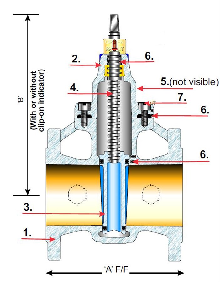
| 1. | Body | Ductile iron |
| 2. | Bonnet | Ductile iron |
| 3. | Wedge | Cast iron GJL-250 |
| 4. | Spindle | Steel 11SMn30 (EN1A) |
| 5. | Pressure relief plug | Steel 11SMn30 (EN1A) |
| 6. | Seals | NBR rubber |
| 7. | Fastenings | Steel gr. 8.8, zinc plated |
Test/Approvals
- Approved according to Kitemark™ GIS/V7-1, certificate KM 518241
- Made in Great Britain
- CE marked according to Pressure Equipment Directive
- UKCA marked according to Pressure Equipment Regulations
Standards
- GIS/V7 Part 1
- Face to face according to EN 558 Table 2 Basic Series 3
- Standard flange drilling to EN1092 (ISO 7005-2), PN 16